-
The Trilogy: Godot Edition - Part 9 - Cutscene camera
Camera movement is stored in
bet.dat. This is a plain text file, so let’s open it up in a text editor.29, 0f,15.1893,15.1893,15.1893, # 28 similar entries ; 12, 0f,0.0,0.0,0.0, # 11 similar entries ; 44, 0f,-36.558,-27.5815,126.056,-36.558,-27.5815,126.056,-36.558,-27.5815,126.056, # 43 similar entries ; 58, 0f,-32.1766,-27.5772,16.4855,-32.1766,-27.5772,16.4855,-32.3134,-27.5332,16.6541, # 57 similar entries ; ;The file is split up into sections, each section starts with a counter which indicates the amount of entries in that section. Each section ends with a
;.In total there are 4 sections: Zoom, Rotation, Position and Target.
- Zoom: The zoom level of the camera
- Rotation: Rotation of the camera
- Position: Position of the camera
- Target: The position the camera targets
Let’s have a look at all 4 sections.
Zoom
29,
0f,15.1893,15.1893,15.1893,
# 28 similar entries
;
The 29 indicates that there are 29 ‘zoom’ entries in this section. The next line is an entry. The first value 0f is the time into the cutscene when the entry happens, in this case the zoom is set to
15.1893right at the beginning of the cutscene. For some reason the value is repeated 3 times, we can ignore the last 2.We can simulate the camera zoom by setting the camera FOV value.
Rotation
12,
0f,0.0,0.0,0.0,
Pretty much the same as zoom; 12 entries, first entry sets the camera rotation to 0.0 degrees at the beginning of the cutscene.
Position
44,
0f,-36.558,-27.5815,126.056,-36.558,-27.5815,126.056,-36.558,-27.5815,126.056,
And again, a similar format. 44 entries, each entry setting the position of the camera, and again the position is repeated 3 times.
Target
58,
0f,-32.1766,-27.5772,16.4855,-32.1766,-27.5772,16.4855,-32.3134,-27.5332,16.6541,
And surprise, surprise, the last section uses the same format. 58 entries with target position data. This is basically the direction the camera aims in.
Animation player
With the data available, we can start with the implementation. We can use Godot’s AnimationPlayer and Animation classes for this. First we’ll have to convert the animation data to an Animation. Some pseudo code:
// Create new animation
Animation animation = new Animation();
// Set the loop mode to None as we only want to play the animation ones.
animation.LoopMode = Animation.LoopModeEnum.None;
// Set the animation length to the full cutscene length
animation.Length = cameraPath.GetLength();

// Create the position data track
int positionTrackIndex = animation.AddTrack(Animation.TrackType.Position3D);
animation.TrackSetPath(positionTrackIndex, "CutsceneCamera");

// Now add all position entries to the position track
foreach (var positionData in cameraPath.PositionEntries)
{
    // Add a position key frame at each timestamp, the animation player will take care of interpolation
    animation.PositionTrackInsertKey(positionTrackIndex, positionData.Timestamp, positionData.Position);
}
With the animation ready we can now create an animation player that can actually play this animation.
// Create an animation library, this is required to play an animation using the animation player
AnimationLibrary cameraAnimLib = new AnimationLibrary();
// Add our cutscene camera animation to the librart
cameraAnimLib.AddAnimation("bet", animation);
// Add the animation library to the animation player
cameraAnimPlayer.AddAnimationLibrary("bet", cameraAnimLib);
// Set the newly created animation as the animation that needs to be played
cameraAnimPlayer.SetCurrentAnimation("bet/bet");
// Start playback
cameraAnimPlayer.Play();
The result:
Great start, we got the camera positioned in the right place, now all we need to do is apply the other properties to the camera.
Well, there is still a tiny problem with that. Godot’s camera doesn’t have properties for “zoom” and “target”, so that will require a little more work.
By adding a script with custom properties we can let the animation player set those properties.
Let’s add a Target property to our
CutsceneCamerascript:private Vector3 _target; [Export] public Vector3 Target { get => _target; set { // Update the local var _target = value; // Set the camera to look at the target relative to the cutscene offset // The LookAt method requires a global space Vector3, while the target value is in the cutscenes local space. LookAt(CutsceneOffset + _target, Vector3.Up); } }Now all we need to do is update our Animation parsing code to also add a “target” track.
 // Create a target track of type 'Value' point it to our 'Target' property
 var targetTrackIndex = animation.AddTrack(Animation.TrackType.Value);
 animation.TrackSetPath(targetTrackIndex, "CutsceneCamera:Target");

 // Add all target entries to the target track
 foreach (var targetData in cameraPath.TargetEntries)
 {
     // Add a target key frame at each timestamp, the animation player will take care of interpolation
     animation.TrackInsertKey(targetTrackIndex, targetData.Timestamp, targetData.Position);
 }
We can do the same for “Zoom” and “Rotation”. Where “Zoom” sets the camera Fov property and rotation updates the camera rotation in degrees, keep in mind that the camera rotation should be applied last to prevent overwriting the “target” rotation.
Et voilà (sorry for the extremely low quality!)
-
The Trilogy: Godot Edition - Part 8 - Cutscene
Sorry babe, I’m an ambitious girl and you, you’re just small time.
In this part of the series we’ll take a look at how cutscenes are handled. We’ll skip the animation implementation for now, as I haven’t figured out the final details on how I want to import them into Godot yet.
Cutscenes in GTA are all rendered in real time in engine. You might have never seen them, but the locations that are used in cutscenes all exist somewhere on the map.
For example the famous intro cutscene of GTA: III happens around here, cleverly hidden behind the mountains:
And GTA: VC’s intro cutscene actually plays inside the Ocean View Hotel. Hidden by Vice Cities new interior system.
The script
To see how those cutscenes are set up we’ll have to dive into the source of the mission script.
If we take a look at GTA: III
intro.scfile, we see the following lines:// **********************************START OF BANK CUTSCENE**************************** MAKE_PLAYER_SAFE_FOR_CUTSCENE Player SET_INTRO_IS_PLAYING TRUE LOAD_COLLISION LEVEL_GENERIC LOAD_SPECIAL_CHARACTER 1 cat LOAD_SPECIAL_CHARACTER 2 colrob LOAD_SPECIAL_CHARACTER 3 miguel LOAD_SPECIAL_CHARACTER 4 playerx LOAD_SPECIAL_MODEL cut_obj1 cs_ban LOAD_SPECIAL_MODEL cut_obj2 bankd LOAD_SPECIAL_MODEL cut_obj3 cs_loot LOAD_SPECIAL_MODEL cut_obj4 colt1 LOAD_SPECIAL_MODEL cut_obj5 cathWe’ll go into the details of the scripting language in another post (there is so much stuff to write about for this game!), for now let’s go over these opcodes one by one.
MAKE_PLAYER_SAFE_FOR_CUTSCENE Playermakes sure that nothing happens to the player during the cutscene. This prevents things like the player dying during the cutscene.SET_INTRO_IS_PLAYINGsets a flag indicating that the intro is playing, we don’t know what this does exactly, but I assume other pieces of the engine use this to determine if the intro is playing.LOAD_COLLISIONloads collision data.LOAD_SPECIAL_CHARACTER 1 catloads the character modelcatinto special character slot1.LOAD_SPECIAL_MODEL cut_obj1 cs_banloadscs_baninto cutscene object slotcut_obj1.
Let’s skip a little bit further in the script to the actual cutscene stuff:
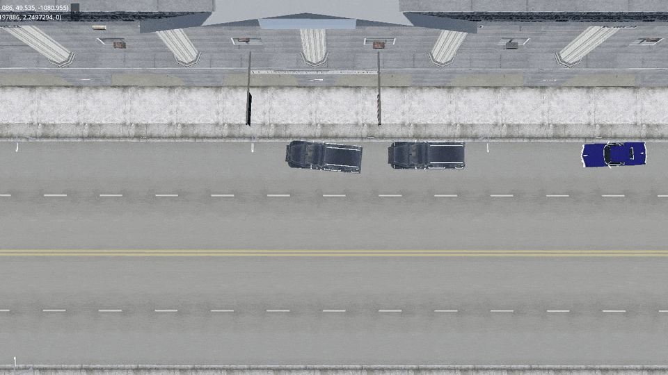
LOAD_CUTSCENE bet
LOAD_SCENE -559.65 1030.56 40.0

SET_CUTSCENE_OFFSET -537.42 1051.204 36.884

CREATE_CUTSCENE_OBJECT PED_SPECIAL4 cs_player
SET_CUTSCENE_ANIM cs_player playerx

// More cutscene object setup

CREATE_CUTSCENE_HEAD cs_cat cut_obj5 cs_cathead
SET_CUTSCENE_HEAD_ANIM cs_cathead cat

// More cutscene object setup

START_CUTSCENE
Again let’s go over the opcodes one by one.
LOAD_CUTSCENELoads the cutscene data fromanim/cuts.img, this includes:bet.ifpthe key frame animation databet.datthe camera movement databet_cat.anmCatalina’s head animation databet.mp3from the audio directory
LOAD_SCENETells the engine to load the scene at a specific locationSET_CUTSCENE_OFFSETCutscene data is based on a local coordinate system (0.0, 0.0, 0.0). To play the cutscene at the correct location an offset is applied.CREATE_CUTSCENE_OBJECT PED_SPECIAL4 cs_playerCreates a new cutscene object with modelPED_SPECIAL4stored in variablecs_playerSET_CUTSCENE_ANIM cs_player playerxApplies theplayerxanimation frombet.ifpto thecs_playercutscene objectCREATE_CUTSCENE_HEAD cs_cat cut_obj5 cs_catheadCreates thecathhead object on thecs_catcutscene object and stores it incs_catheadSET_CUTSCENE_HEAD_ANIMApplies thecatanimation frombet_cat.anmto Catalina’s head.START_CUTSCENEStarts the cutscene.
That’s quite some setup to play a single cutscene! To replicate the cutscene we have to do the same steps in Godot. In the next few posts I’ll describe the steps to get this cutscene playing.
The map
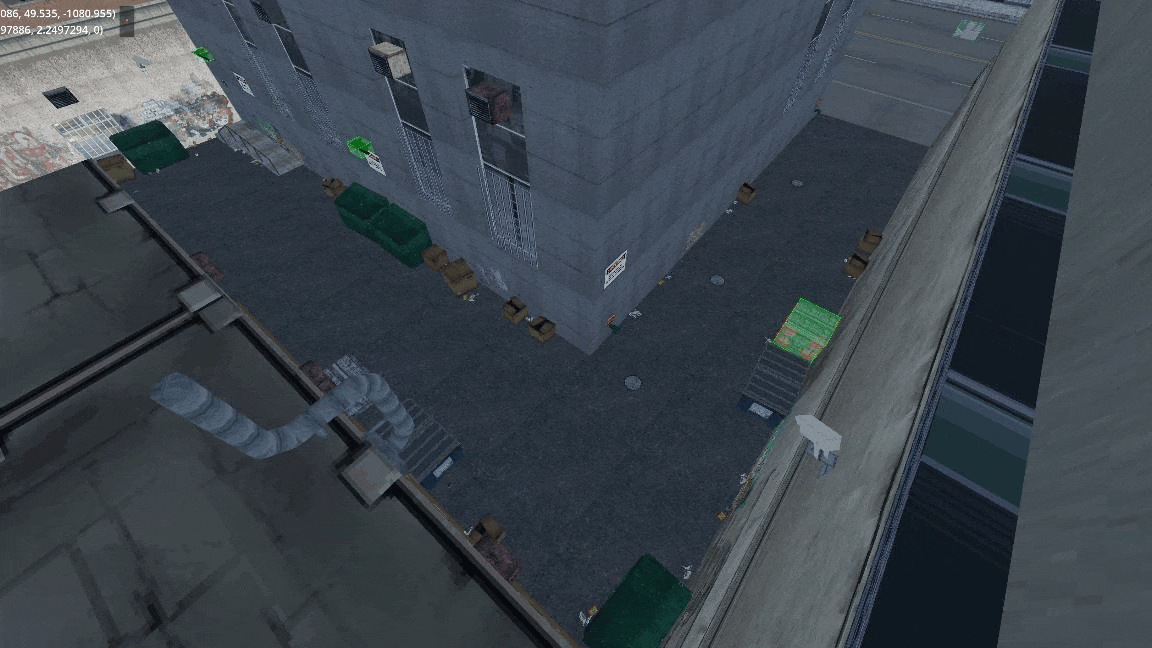
First of all we have to make sure the map is loaded, the intro cutscene is located at
-559.65 1030.56 40.0which should load if we load the map data from thelandswdirectory.
Rendering is a bit off, but it’s good enough for now!
In the next post we’ll take a look at camera movement data found in
bet.dat. -
The Trilogy: Godot Edition - Part 7 - Textures
It’s time to discuss textures. The way materials are handled in the Trilogy are much simpler then materials these days. No fancy normal maps or specular maps. Just a simple texture and perhaps an alpha texture for some translucent models.
Textures are stored in TXD files aka TeXture Dictionary.
ℹ️
Fun fact, GTA IV uses similar files but calls them WTD on Windows (Windows Texture Dictionary) and uses a different first character depending on the platform.
These texture dictionary files use the same format as DFF files as they are RenderWare based. Let’s have a look at a TXD file.
File structure
Because TXD files are just RenderWare files, we can view the file structure in the same tools as DFF files.
The tree of LoadSC0 looks like this:
RwTextureDictionary
├── RwTextureNative
│   └── RwExtension
└── RwExtension
TextureDictionary
This is the root section of TXD files, it contains the number of textures in the archive.
TextureNative
For each texture inside the archive there is a TextureNative section. This section contains info about the format of the texture data and the texture data itself.
Texture format
In this section we will go over some of the texture formats. A detailed description of the possible texture formats can be found at gtamods.com.
Mapping most of the texture formats to their Godot equivalent is quite easy:
⚠️️ Note: This table is incomplete.
Compression Raster format Godot DXT1 FORMAT_1555 ❌ Unsupported* DXT1 FORMAT_565 DXT1 - FORMAT_565 Rgb565 - FORMAT_4444 ❔* - FORMAT_LUM8 L8 - FORMAT_8888 Rgba8 - FORMAT_888 Rgb8 - FORMAT_555 ❔* - FORMAT_EXT_AUTO_MIPMAP Image.GenerateMipMaps() - FORMAT_EXT_PAL8 ❌ Unsupported** - FORMAT_EXT_PAL4 ❌ Unsupported** - FORMAT_EXT_MIPMAP Flag that indicates that mipmaps are included in the data *We’ll get to this one in a later post**See section on palette textures below
With that in mind it’s pretty straightforward to turn TXD entries into Godot textures.
// texData contains our texture native section struct
int mipMapLevel = 0

ImageTexture.CreateFromImage(
    Image.CreateFromData(
        (int)texData.width,
        (int)texData.height,
        false, // Set depending on mipmap flags
        texData.getFormat(), // Performs the mapping from the above table
        texData.textureData[mipMapLevel] // Perform this for each mipmap level
    )
)
Palette Textures
If we take a look at GTA: III we notice that a lot of textures use a palette. This means that the texture is split into 2 pieces of data. The regular texture data contains an array of indices in a range of 0 - 255. These indices point to the palette texture which contain the actual color data. It’s as simple as paint by number, lets take a look at the following example:
Index texture Palette texture Result 
+ 
= 
Godot (and modern graphic cards) don’t support this natively. We have three options to solve this:
- Transform the texture data at runtime. Create a RGB(A) byte buffer that has the size of the texture, loop through all indices and set the color accordingly.
- Transform the texture data at first run and store it on the users harddrive in the new format.
- A custom shader that performs the lookup.
In my implementation I went for option #3.
We’ll have to create a shader that takes 2 textures. One for the index texture and one for the palette texture.
uniform sampler2D index_texture : filter_nearest; // Using linear would mess up the indices
uniform sampler2D palette_texture : source_color;
Ideally our index texture would be of type
usampler2Das our index range is anuintbetween 0 and 255, but due to a bug in Godot this is not possible, instead we’ll need to transform the index to anuintinside the shader.To look up the index of the color pixel we have to retrieve the value from the index_texture. Due to the previously mentioned bug we then need to multiply the result by 255.0:
uint tex_index = uint(texture(index_texture, UV).r * 255.0);With the index we can now perform a lookup of the actual color that is used inside the palette texture.
Instead of
texturewhich takes normalized UV coordinates, we can usetexelFetchwhich takes pixel coordinates.vec3 tex_color = texelFetch(palette_texture, ivec2(int(tex_index), 0), 0).rgb;And that’s pretty much it. My final shader code:
shader_type spatial;

render_mode cull_front;

uniform sampler2D index_texture : filter_nearest;
uniform sampler2D palette_texture : source_color;
uniform vec3 albedo_color : source_color = vec3(1.0, 1.0, 1.0);

void fragment() {
    uint tex_index = uint(texture(index_texture, UV).r * 255.0);
    vec3 tex_color = texelFetch(palette_texture, ivec2(int(tex_index), 0), 0).rgb;

    vec3 material_color = albedo_color.rgb;

    ALBEDO = tex_color * material_color;
}
And the result:
-
The Trilogy: Godot Edition - Part 6 - Map collision
My problem
We got some nice visuals, but when we place our “player” in front of the golf course, he’ll just fall through the map.
To solve this we need to load the collision data for each map object, but how and when is this loaded? When we looked at the map files there was no mention of collision data except for these two lines:
COLFILE 0 MODELS\COLL\VEHICLES.COL
COLFILE 0 MODELS\COLL\WEAPONS.COL
Looking at the name of those collision files I don’t expect them to contain golf collision data except for a
CaddyandGolfclub.My guess
I do have an idea of how collision data is loaded, but that’s all based on the following best guesses: Back in the day when I was into modding, I had to make quite a few custom collisions. There are a couple of steps you had to take to add collision to your model:
- Create a coll archive
- Add a coll entry with the same name as your model
- Add the coll archive to the IMG archive
That seems easy enough, the game just looks for a coll entry with the same name as our model. But, when does the game load these?
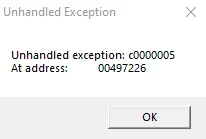
Well, back in the day it was also not uncommon to accidentally create a corrupt collision file. When you imported a corrupt coll archive the game would crash during loading with a nice popup similar to this one.
My guess; during loading, all collision archives inside the IMG file are read and loaded into memory or at least put into some kind of file table.
With the how and when figured out we can try to do the same in our implementation.
My solution
After loading an IMG file, I search for all
.colentries in the file table and load them into memory, in my case a Dictionary for easy model name to collision lookup.Something like the following pseudocode.
private Dictionary<string, Coll> _collisionData = new();

public void Load()
{
    Image img = LoadImg("gta3.img");
    var collisionEntries = img.FindByType("col");
    foreach (var entry in collisionEntries)
    {
        var collFile = LoadColFile(img, entry);
        // Add all entries in the collFile to the dictionary
    }
}
And as always the result:
-
The Trilogy: Godot Edition - Part 5 - Map loading
⚠️️ A little disclaimer:
Godot currently doesn’t provide streaming capabilities out of the box. But, the games we try to simulate are very old and hardware has improved immensely in the past 25(!) years. So we might actually get away with just rendering the map without implementing any streaming.
For now, we’ll take the most naive, non optimized, approach (remember I am not an expert at Godot nor at Game dev) and might improve our implementation at a later stage.
With that out of the way, let’s get started!
IPL Loading
In our example we’ll be using Vice City’s golf course. The golf course is located near the games center (0.0, 0.0, 0.0) which makes it convenient for quick testing.
As described in my previous post the placement of objects is defined in IPL files. This file contains the location data of an object. Which means we should be able to display a bunch of boxes at the location data and already get a feel of the map.
The easiest way to display a lot of boxes at certain positions is by just adding
MeshInstance3Dnodes to a scene, but this is a learning experience so we can do it a bit more efficiently. We can useMultiMeshInstance3D, a node specifically created to render repeating meshes efficiently, perfect for our use case!Some example code, this assumes we have an IPL file loaded into memory that contains an array of instances.
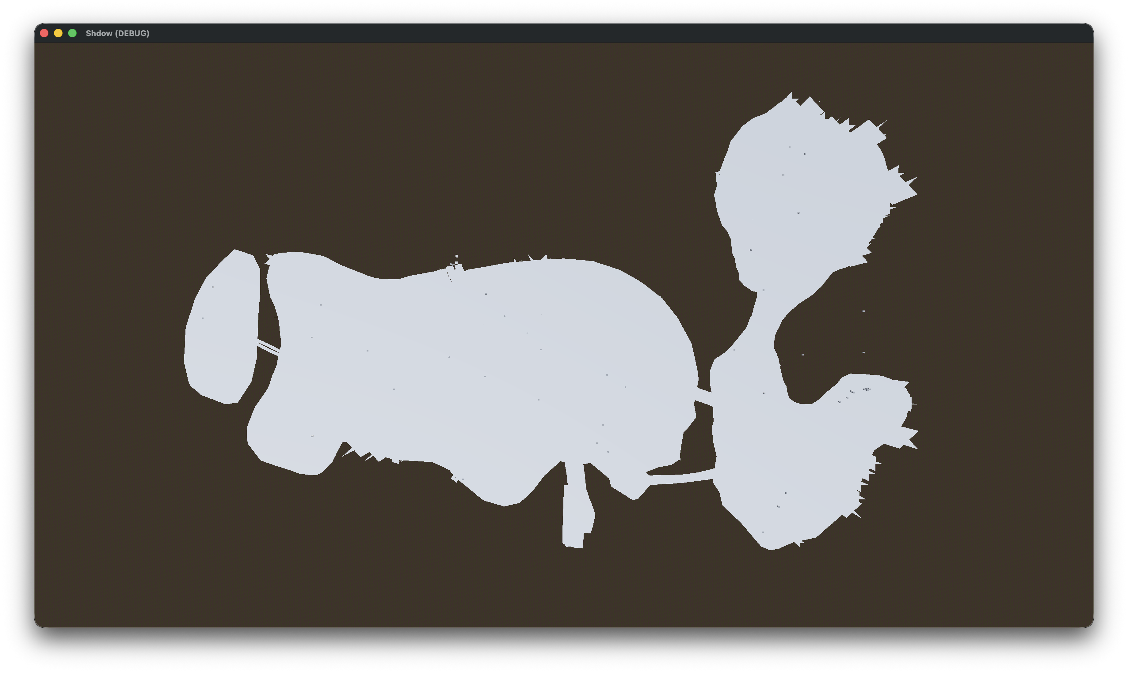
// Create a multi mesh
MultiMesh multiMesh = new MultiMesh
{
    TransformFormat = MultiMesh.TransformFormatEnum.Transform3D,    // Sets up our multimesh to support 3D transforms
    InstanceCount = ipl.Instances.Count,                            // Set the amount of instances to our IPL instance count
    Mesh = new BoxMesh                                              // Set the mesh to a simple box
    {
        Size = new Vector3(2.0f, 2.0f, 2.0f),
    }
};

// Loop through our IPL instances and set the transforms in the multimesh
for (var i = 0; i < ipl.Instances.Count; i++)
{
    var inst = ipl.Instances[i];
    multiMesh.SetInstanceTransform(i, new Transform3D(this.Basis, inst.Position));  // Set the transform to our instance position (Ignoring rotation and scale for now)
}

MultiMeshInstance3D multiMeshNode = new MultiMeshInstance3D();  // Create a MultiMeshInstance3D node
multiMeshNode.Multimesh = multiMesh;                            // Attach our multi mesh to the node
AddChild(multiMeshNode);                                        // Add the MultiMeshInstance3D node to the scene
The result:
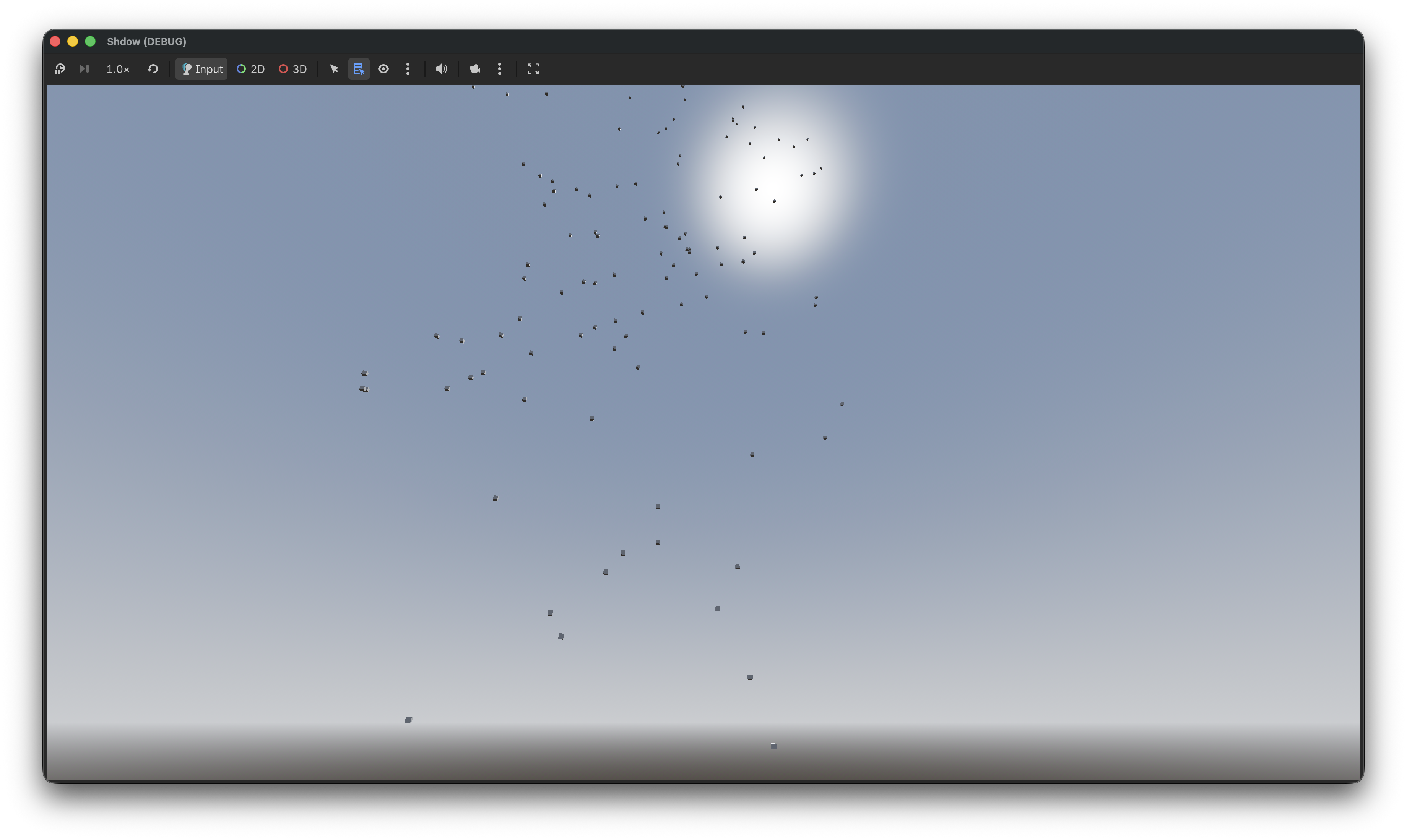
Hmm something is up, and it’s not Z! If you didn’t get that joke no worries I’ll explain it.
The coordinate system
Godot and GTA use a different coordinate system! Freya Holmer created an amazing image that explains the difference in coordinate systems and it’s usages.
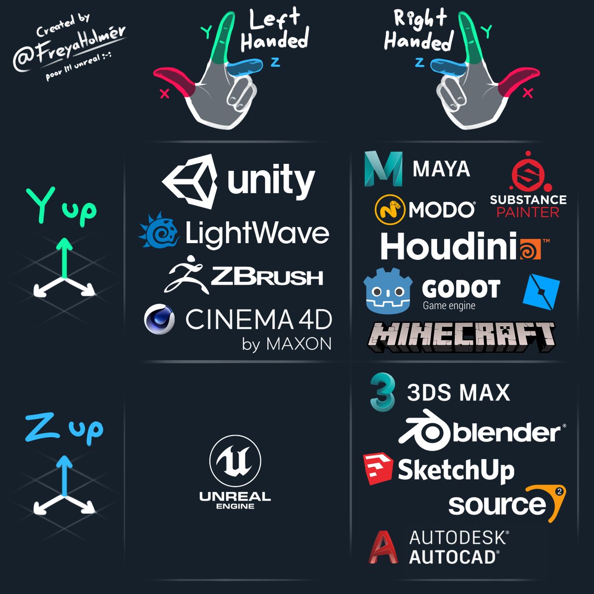
As you can see in the above image, Godot uses the
Right HandedY-Upcoordinate system. But, which one does GTA use? Well the modeling / mapping tool used for the original trilogy was 3DS Max, which matches with the coordinate system used by GTA, theRight HandedZ-Upcoordinate system.There are multiple options to switch between those coordinate systems.
- Swap the Y and Z values of every Vector3 when loading it into Godot.
- Rotate every object individually
- Rotate the camera
- Rotate the world root node
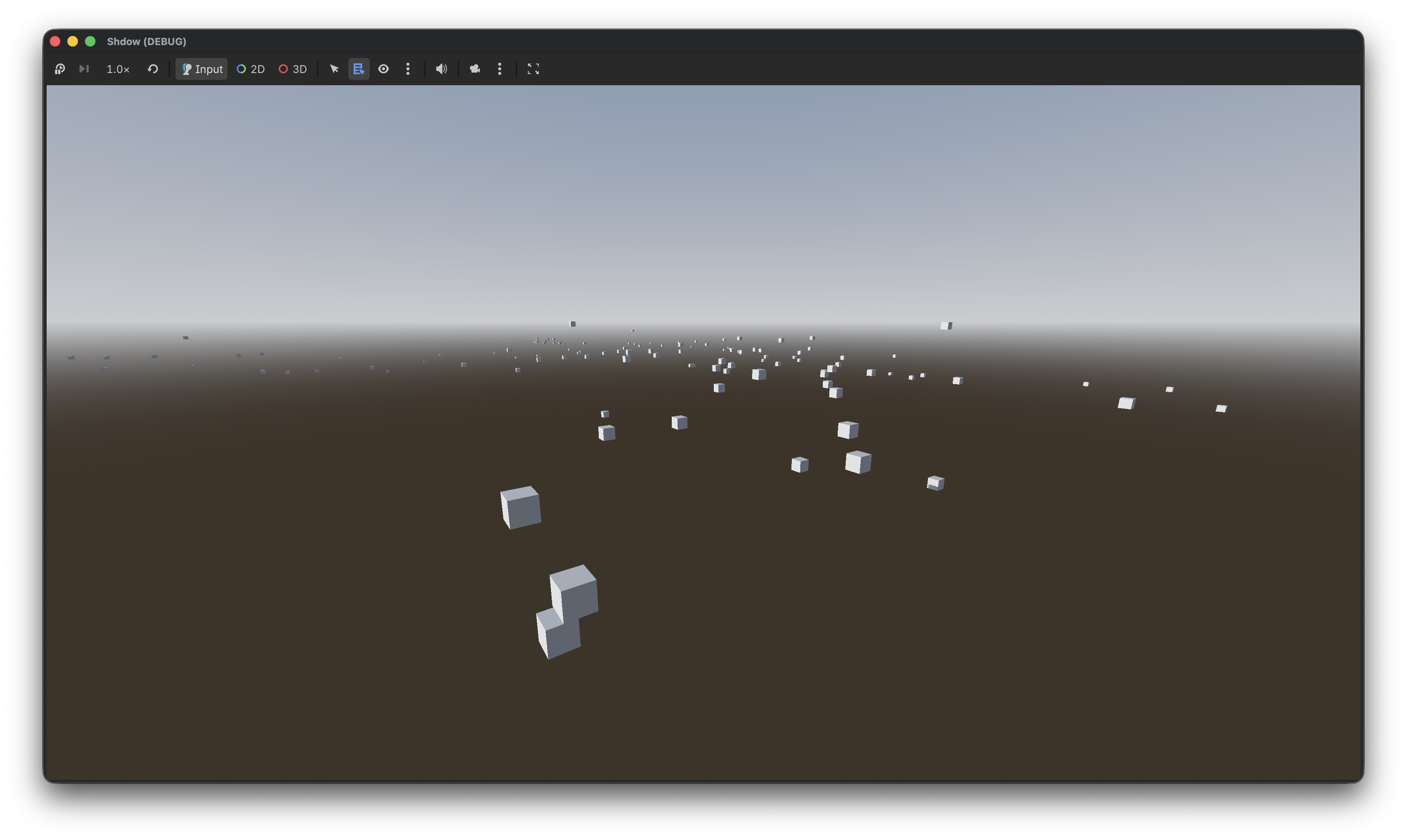
And to be honest I am not sure what the best approach is. Option #1 sounds easy, but will probably end up causing issues when Z is not used in a Vector3 (IE: By the script) and might not work nicely with rotations. Option #2 sounds like a lot of work. So I guess that leaves us with options #3 and #4. For now, I’ll use option #4 as that is the easiest.
After rotating the world 90 degrees we end up with the following, which already looks a lot better!
All nice and dandy those boxes, but we’d like to actually see the map. To do that we’ll need to load the IDE first as those define which model / textures should be used.
But first we’ll need to refactor our box rendering code. MultiMesh is great for rendering the same mesh multiple times, but in our case we want to render a different mesh for each instance. So let’s rewrite our box rendering code to use regular nodes.
// Create our box mesh
Mesh mesh = new BoxMesh
{
    Size = new Vector3(2.0f, 2.0f, 2.0f)
};

// Loop through our IPL instances and create a new MeshInstance3D with our box mesh at the instance position
for (var i = 0; i < ipl.Instances.Count; i++)
{
    var inst = ipl.Instances[i];
    var meshInstance = new MeshInstance3D();
    meshInstance.SetMesh(mesh);
    meshInstance.Position = inst.Position;
    AddChild(meshInstance);
}
The result of this code is exactly the same as the MultiMesh implementation except it uses a few more draw calls, and it allows us to render different meshes for each instance.
IDE loading
To replace our boxes with meshes we have to load the IDE file as those define which model belongs to each ID.
Let’s parse the IDE file and create some kind of look up table of definitions, this could be a simple array where the index is the ID of a definition or some kind of Dictionary. Now that we have an easy way to access the definition we can retrieve the model information, and use that to load our mesh.
The updated code should look something like this pseudocode:
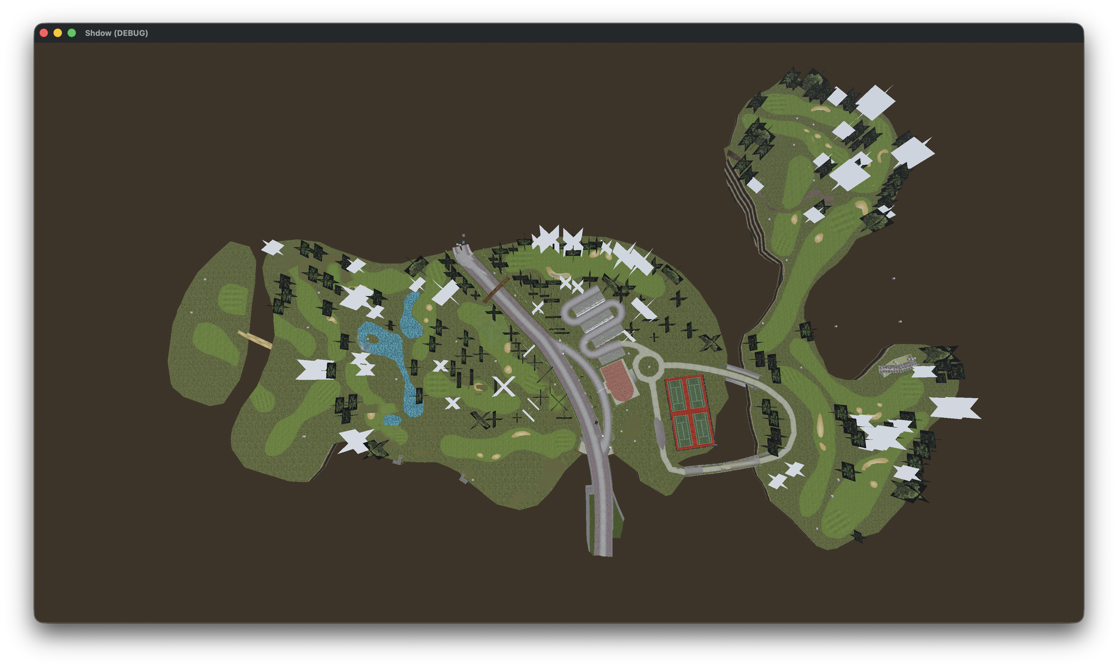
public void _Ready() {
    // Load IDE and create the definition look up table
    LoadIDE("data/maps/golf/golf.ide")
    // Load IPL
    LoadIPL("data/maps/golf/golf.ipl")
}

public void LoadIpl(string path) {
    // Parse the IPL file into an object
    var ipl = IplLoader.Load(path);

    // Loop through our IPL instances
    for (var i = 0; i < ipl.Instances.Count; i++)
    {
        var inst = ipl.Instances[i];

        // Instead of creating the BoxMesh we load the model according to the definition
        var model = LoadModelForId(inst.Id);

        // Set the position of the model
        model.Position = inst.Position;

        // Add the model to the scene
        AddChild(model);
    }
}

private RwNode LoadModelForId(int id)
{
    // Fetch definition from lookup table (Note that some definitions might be missing due to us only loading golf.ide)
    // Load model according to definition (as described in part 1/2 of this series)
}
This should already give us something recognizable.
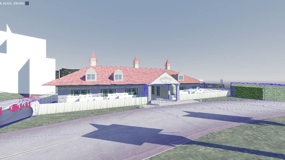
And with textures. (I have to write about texture loading at some point!)
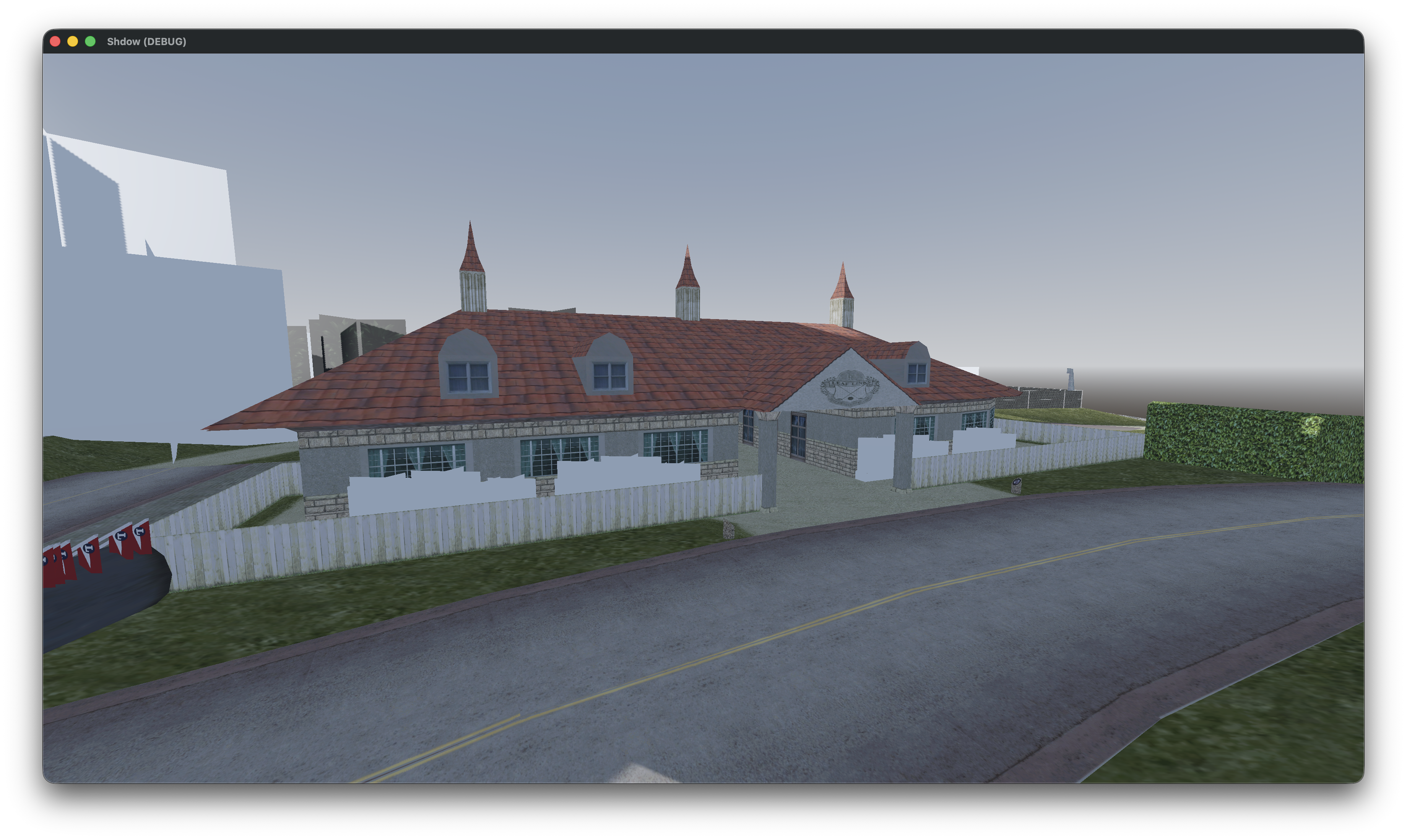
There are some things not quite right though. If we for example take a look at those bushes (besides the fact that they are textureless) they are also misplaced.
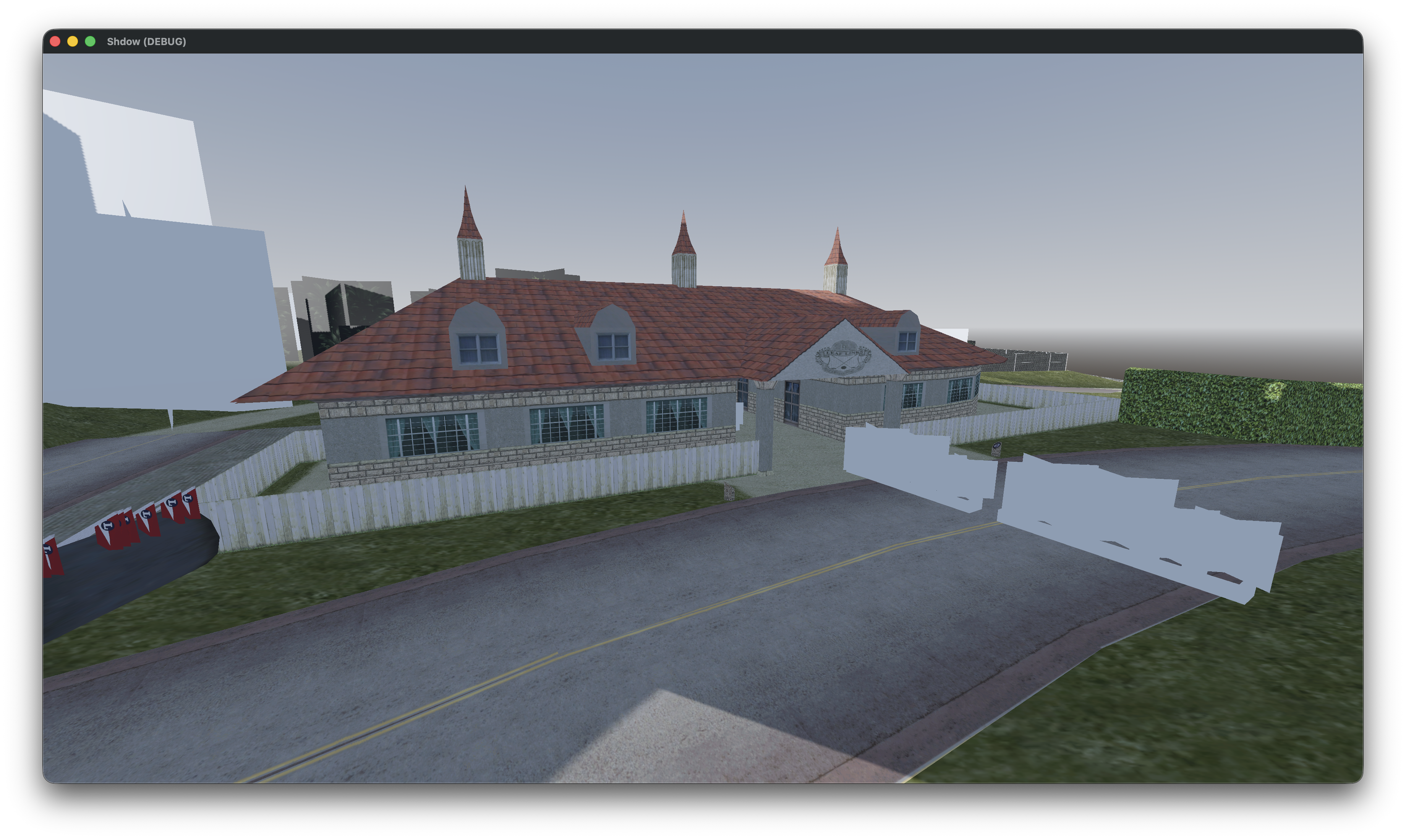
We forgot to apply the rotation! Let’s update the code to also apply the rotation to our model.
// Set the position of the model
model.Position = inst.Position;

// Set the rotation of the model
model.Quaternion = inst.Quaternion
The result (no this didn’t magically fix our missing textures):
That’s it for this post, in the next one we’ll also load collision so we don’t fall through the map.